EN
EN
What is Aluminum Profile and How Does It Work?
2026/09/30
Source aluminum profiles for versatile modular framing. Learn extrusion mechanics, strength benefits & corrosion resistance. Request details.

2026/09/29
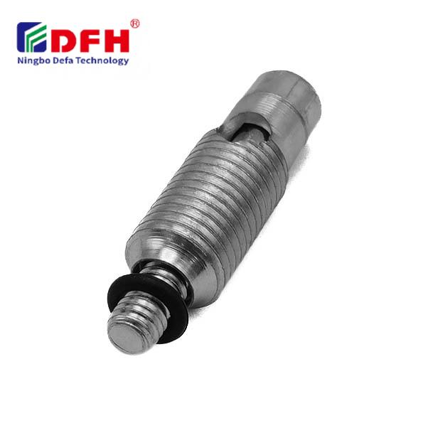
Installing Plate Connectors in frame systems requires precision, planning, and adherence to structural engineering standards. These critical components serve as the backbone of modular connection systems, ensuring that load-bearing junction components function reliably under sustained stress. Whether you're assembling industrial structures, modular buildings, or heavy-duty frameworks, understanding the installation process is essential for achieving structural integrity and long-term durability.
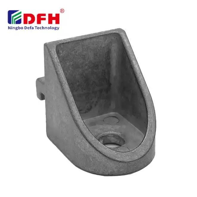
Plate connectors function as versatile fastening components that link frame members at critical junction points. By distributing loads evenly across connection zones, structural fastening solutions using plate connectors prevent stress concentration and potential failure points. This installation guide walks you through the entire process, from material preparation to final torque verification, ensuring your frame systems achieve optimal performance and compliance with industry standards.
Before beginning any installation work, thoroughly examine the structural fastening solutions specification sheet for your specific plate connectors. Verify that plate dimensions, bolt hole sizes, material grade, and load ratings match your frame design requirements. Check surface finish quality, ensuring the connector coating remains intact and free from corrosion or damage. Document the connection orientation and any directional markings that indicate load paths or preferred installation angles.
Load-bearing junction components must align precisely with frame member axes to function as intended. Measure frame member cross-sections and confirm that connector attachment points align with structural requirements. Review engineering drawings for connection sequencing, bolt installation order, and any special assembly procedures specific to your modular connection systems design.
Clean all contact surfaces where plate connectors will attach to frame members, removing rust, oil, paint, and contaminants using wire brushes or appropriate cleaning agents. Surface preparation directly impacts load transfer efficiency and structural fastening solutions reliability. Position frame members on a level, stable work surface and use temporary bracing to prevent shifting during plate connector installation. Apply marking fluid or chalk to outline connector placement, ensuring alignment holes receive proper spacing and positioning.
Position the plate connector against the frame member and ensure all bolt holes align perfectly with corresponding holes in the load-bearing junction components. Insert alignment pins through select bolt holes first, securing the connector in exact position before full bolt installation. These alignment pins prevent accidental shifting during the fastening process and maintain precise connection geometry required by structural fastening solutions specifications.
Insert bolts through aligned holes, beginning from the center and working outward. This radial installation pattern for modular connection systems prevents connector tilting or skewing. Hand-tighten all bolts initially to snug contact, ensuring the plate connector remains properly seated against the frame member surface. Check alignment and position once more before proceeding to torque specification.
Apply torque in a cross-cross pattern, similar to tightening wheel nuts, to distribute clamping load evenly across all load-bearing junction components. Begin with approximately 40 percent of specified torque, then progressively increase to final specification in 25 percent increments. This graduated approach allows the connection to settle and prevents overtightening early bolts that would reduce contact pressure on others.
Use a calibrated torque wrench for all final tightening operations, ensuring each bolt reaches exact specification. Verify that plate connectors remain flush against frame members without gaps or distortion. Inspect bolt head seating and washer contact, confirming proper load distribution across connection zones. For critical modular connection systems applications, document torque values and mark each bolt with identification paint or tape for verification audits.
After completing all structural fastening solutions tightening, perform a thorough visual inspection of plate connectors, examining for cracks, deformation, or separation from frame members. Check that no bolt heads spin freely or exhibit signs of loosening. Apply moderate manual pressure to the connection, confirming rigid response and confirming load-bearing junction components function as a unified structural unit. Verify that all bolts remain torqued to specification using a calibrated torque wrench in verification mode.
Photograph all completed connections for documentation and quality records. Compare installation results against engineering drawings and specification requirements. Mark any discrepancies or modifications for engineering review before structural loading begins. For load-critical applications, perform ultrasonic testing or magnetic particle inspection on plate connectors to detect subsurface defects or material issues.
Apply controlled test loads progressively, beginning at 25 percent of design capacity and increasing incrementally to full working load. Monitor connection behavior, observing for excessive deflection, noise, or movement indicating inadequate fastening or material failure. Install strain gauges on select connections within modular connection systems to measure actual stress distribution and validate alignment with design predictions.
Document load test results, including maximum displacement, permanent set measurements, and any anomalies observed during testing. Verify that structural fastening solutions connections demonstrate linear elastic behavior and return to original dimensions after load removal. Conduct final re-torque verification 24 hours after installation, as some settling naturally occurs in new connections. This final check ensures plate connectors maintain full clamping force and load-bearing junction components remain optimally connected.
Torque specifications vary based on bolt grade, frame material, and connection geometry. Steel frame connections typically use higher torque values than aluminum or composite systems. Consult the specific torque chart provided with your modular connection systems documentation, which accounts for material properties and structural fastening solutions design. When specifications appear ambiguous, contact the connector manufacturer or consulting engineer for clarification before proceeding.
Use alignment pins through select holes during initial positioning, and maintain these pins until all bolts reach at least 50 percent of final torque specification. Digital levels and laser alignment tools help verify orientation accuracy throughout the installation process. For critical modular connection systems applications, consider using fixture plates or alignment guides designed specifically for your connector configuration to ensure precise geometry.
Plate connectors can be reused if they remain undamaged during disassembly and show no signs of permanent deformation, cracking, or thread damage on bolt holes. Inspect connectors thoroughly before reinstallation, ensuring they meet original structural fastening solutions specifications. Replace any components showing wear, corrosion, or damage, as compromised load-bearing junction components reduce connection reliability and safety margins in your frame systems.
2026/09/30
Source aluminum profiles for versatile modular framing. Learn extrusion mechanics, strength benefits & corrosion resistance. Request details.
2026/09/30
Source aluminum profiles for construction projects. Learn structural framing, cladding & window benefits for maximum ROI. Download guide.
2026/09/30
Source optimal aluminum profile sizing techniques. Evaluate load, space, alloy, environment & cost factors to prevent deflection. Download guide.
2026/09/30
Struggling with fastener failures or rework? Master screw sizing by diameter, pitch, material, and load—plus industry-specific standards. Optimize reliability & compliance now.
2026/09/30
Source aluminum profiles for industrial engineering. Discover strength-to-weight ratios, corrosion resistance & 30% cost savings. Download guide.
2026/09/30
Source heat-resistant aluminum profile systems. Master thermal expansion science & stress management strategies for industrial builds. Download guide.