EN
EN
What is Aluminum Profile and How Does It Work?
2026/09/30
Source aluminum profiles for versatile modular framing. Learn extrusion mechanics, strength benefits & corrosion resistance. Request details.

2026/09/08
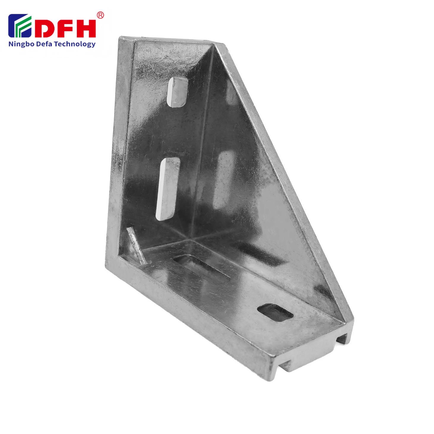
Installing End Connectors safely requires careful planning, proper equipment, and a systematic approach to avoid electrical hazards and installation failures. Whether you're working with industrial cables, electrical systems, or telecommunication infrastructure, the way you handle cable end connectors directly impacts system reliability, safety, and longevity. Many installation mistakes stem from rushing the process, using incorrect connector terminals, or failing to follow manufacturer specifications. This guide walks you through the essential steps to ensure every connection is secure, compliant, and built to last.
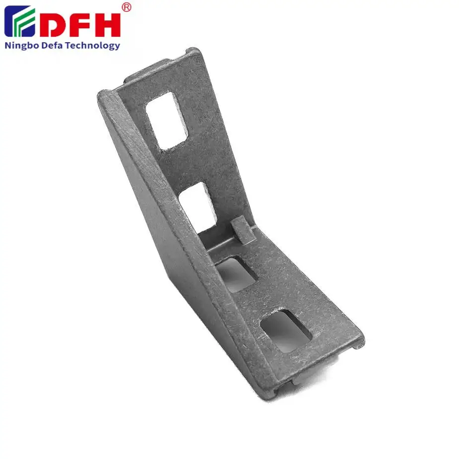
Safety when installing connection hardware extends beyond the physical act of fastening components. It encompasses electrical safety, mechanical stability, environmental protection, and compliance with industry standards. Improper installation of cable end connectors can lead to poor contact resistance, voltage drops, equipment failure, and fire hazards. Understanding the fundamentals of connector terminals and their proper deployment will help you avoid costly downtime and protect personnel on the job site.
Cable end connectors serve as the interface between electrical conductors and equipment terminals, allowing power and signal transmission to occur with minimal resistance. Connector terminals come in various styles including ring terminals, spade terminals, and pin connectors, each designed for specific applications and environmental conditions. Connection hardware acts as the mechanical fastening element that holds end connectors securely in place against vibration, thermal cycling, and operational stress. Understanding the type of cable end connectors required for your application prevents mismatches that compromise both safety and performance.
Selecting the right connector terminals starts with identifying your cable gauge, voltage rating, current capacity, and environmental exposure. Using undersized connection hardware for oversized cables creates bottlenecks in electrical flow and generates heat. Conversely, oversized end connectors on small conductors may not maintain adequate contact pressure. Matching end connectors to both the cable specification and the terminal stud diameter ensures uniform electrical distribution and mechanical reliability throughout the system.
Before you begin, assemble all necessary tools including wire strippers, crimpers designed for your specific connector terminals, torque wrenches, and safety equipment such as insulated gloves and eye protection. Verify that your connection hardware matches the cable gauge and terminal size requirements outlined in the equipment manual. Inspect all cable end connectors for physical damage, corrosion, or manufacturing defects that could compromise the installation. Keep a copy of the relevant electrical codes and manufacturer documentation within reach throughout the process.
Establish a clean, well-lit workspace free of moisture and contaminants that could interfere with connection quality. Measure and mark the cable to ensure accurate length before stripping insulation. Strip only the amount of conductor insulation necessary to accommodate the connector terminals without exposing excess bare copper, which increases the risk of shorts and corrosion. For cable end connectors, maintaining proper insulation coverage protects the connection hardware from environmental exposure and mechanical damage.
Insert the prepared cable conductor into the barrel of your selected cable end connectors until it reaches the designated depth mark. Position the connector terminals in the crimper tool according to manufacturer specifications, ensuring the tool is properly calibrated for your cable gauge. Apply steady, even pressure to the crimper handle until you hear or feel the crimp cycle complete, creating a permanent bond between the conductor and the end connectors. A properly crimped connection demonstrates no gaps between the conductor and the barrel interior and resists pulling apart under moderate force.
After crimping, position the cable end connectors onto the destination terminal stud, ensuring the connector terminals align squarely with the mounting surface. Insert the fastening bolt or stud screw through the connection hardware and hand-tighten it initially to seat the connector without strain. Using a calibrated torque wrench, apply the specified torque value to the bolt while holding the terminal stud stationary to prevent rotation. This step is critical because insufficient torque allows vibration-induced loosening, while excessive torque can damage the end connectors or crush the conductor inside the barrel.
After fastening end connectors, visually inspect the installation for proper seating, alignment, and any signs of damage to the cable end connectors or surrounding components. Perform a gentle pull test to confirm the connection hardware is secure and the connector terminals resist movement. For outdoor or harsh environments, apply protective coatings such as dielectric grease to the connection hardware to prevent corrosion and moisture intrusion. Testing electrical continuity using a multimeter confirms that the cable end connectors and connector terminals have achieved the low-resistance contact necessary for safe operation.
One of the most frequent errors occurs when installers use the wrong gauge of cable end connectors for their conductors or select connection hardware that does not match the terminal stud diameter. This mismatch creates mechanical instability and increases contact resistance, generating heat at the connection point. Always verify that your connector terminals are rated for the exact cable size and voltage of your application before beginning work.
Inadequate crimping force fails to establish a permanent bond between the conductor and the barrel of cable end connectors, while excessive force can fracture the internal strands and weaken the connection. Using hand-operated crimpers for large-gauge conductors often produces inconsistent results; hydraulic or ratcheting crimpers designed for your specific connector terminals deliver more reliable results. Take time to practice your crimping technique on test samples before working on critical installations.
Always consult the equipment manufacturer's documentation or the connection hardware packaging for the specified torque value, as this varies by terminal material, cable end connectors size, and bolt type. Most industrial applications range from 15 to 50 foot-pounds depending on the stud diameter and application class. Using a calibrated torque wrench ensures you achieve the correct clamping force without over-tightening or under-tightening the cable end connectors.
Perform visual inspection for proper seating, check that connector terminals show no gaps or deformation, measure electrical continuity with a multimeter to confirm low resistance, and conduct thermal imaging after the system operates under load to detect hot spots. If you observe corrosion, loose fasteners, or high resistance readings, disassemble and reinstall the end connectors using proper technique and matching connection hardware.
Temperature cycling, moisture, salt spray, UV exposure, and vibration all accelerate corrosion and loosening of cable end connectors and connection hardware over time. For installations in harsh environments, specify connector terminals with plating designed for corrosion resistance, apply protective coatings, and use lock washers or thread-locking compounds to prevent vibration-induced loosening of your end connectors.
2026/09/30
Source aluminum profiles for versatile modular framing. Learn extrusion mechanics, strength benefits & corrosion resistance. Request details.
2026/09/30
Source aluminum profiles for construction projects. Learn structural framing, cladding & window benefits for maximum ROI. Download guide.
2026/09/30
Source optimal aluminum profile sizing techniques. Evaluate load, space, alloy, environment & cost factors to prevent deflection. Download guide.
2026/09/30
Struggling with fastener failures or rework? Master screw sizing by diameter, pitch, material, and load—plus industry-specific standards. Optimize reliability & compliance now.
2026/09/30
Source aluminum profiles for industrial engineering. Discover strength-to-weight ratios, corrosion resistance & 30% cost savings. Download guide.
2026/09/30
Source heat-resistant aluminum profile systems. Master thermal expansion science & stress management strategies for industrial builds. Download guide.