EN
EN
What is Aluminum Profile and How Does It Work?
2026/09/30
Source aluminum profiles for versatile modular framing. Learn extrusion mechanics, strength benefits & corrosion resistance. Request details.

2026/09/03
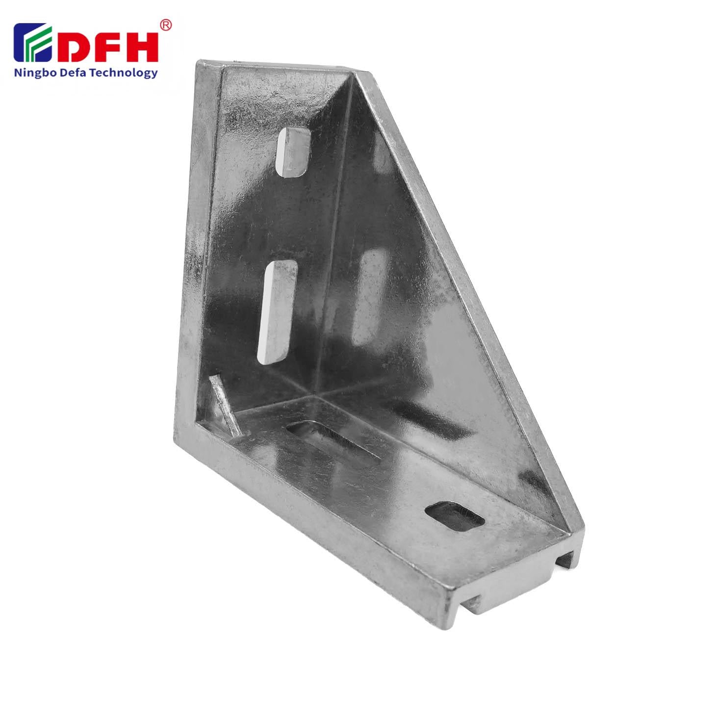
Installing inner connectors requires careful attention to safety protocols and proper assembly techniques to ensure structural integrity and worker protection. Whether you are working with profile joint systems in manufacturing, construction, or industrial applications, understanding the correct installation procedures for inner connectors is essential to prevent accidents, product failure, and costly downtime. This guide walks you through the critical steps, safety considerations, and best practices for installing internal connection hardware efficiently and securely.
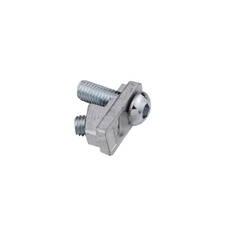
Safety is the top priority when working with inner connectors and modular assembly components. Proper installation protects both personnel and equipment, extends the service life of your assemblies, and maintains compliance with workplace safety standards. By following established protocols and understanding the mechanics of your connection hardware, you can achieve reliable, durable assemblies that perform as intended.
Before you begin installation, you must fully understand the specifications and design of your Inner Connectors. Internal connection hardware varies significantly in material composition, load capacity, thread types, and dimensional tolerances. Review the technical documentation provided by the manufacturer to identify critical measurements, material grades, and recommended torque specifications. Understanding whether your modular assembly components feature standard metric threading, specialized lock features, or powder-metallurgy construction ensures you select appropriate tools and follow the correct assembly sequence.
Profile joint systems operate under specific design parameters. Each connector type has maximum load ratings, temperature ranges, and environmental limitations that directly affect installation safety. Misidentifying connector specifications or ignoring compatibility requirements can result in premature failure, structural weakness, or safety hazards during operation. Take time to compare your hardware against manufacturer specifications and cross-reference with your assembly design requirements before commencing work.
Proper tooling is fundamental to safe installation of internal connection hardware. You will need precision calibrated torque wrenches, Allen keys or hex sockets sized to match your fastener specifications, and safety equipment including gloves, safety glasses, and work surface protection. For modular assembly components involving aluminum profiles or delicate surfaces, use soft-faced mallets and wooden or plastic alignment blocks to prevent surface damage. Never use oversized tools or apply excessive force, as this risks stripping fastener heads, damaging threads, or causing the connector to fail during installation.
Inspect all tools before use to ensure they are in good condition, properly calibrated, and free from wear or damage. A damaged torque wrench cannot deliver accurate fastening force, leading to under-tightened connections that may loosen or over-tightened fasteners that crack or deform. Store profile joint systems and connection hardware in clean, dry conditions to prevent corrosion, contamination, or dimensional changes that compromise fit and performance during assembly.
Begin by carefully positioning all components of your modular assembly components in their final alignment before tightening any fasteners. Inner connectors must seat fully against mating surfaces with no gaps, misalignment, or binding that suggests incorrect orientation. Use alignment fixtures, guide pins, or temporary fasteners to hold parts in correct position. For profile joint systems, verify that aluminum profile channels, T-slots, or other receiving features are clean and free from debris that could prevent proper seating of the connection hardware.
Never force internal connection hardware into position. If resistance occurs, stop and investigate the cause before applying additional force. Common issues include mismatched thread starts, contamination on fastener surfaces, or dimensional incompatibility between mating parts. Gentle hand-tightening followed by careful examination ensures that all components align correctly before power tools or maximum torque values are applied. This preventive step avoids damage to fasteners, threads, or mating surfaces that become extremely difficult and expensive to repair.
Once alignment is confirmed, begin fastening your inner connectors using graduated torque application. Start with hand-tightening to establish solid contact between all mating surfaces, then use your calibrated torque wrench to apply the manufacturer-specified fastening force. For profile joint systems with multiple connection points, tighten fasteners in a balanced pattern rather than fully tightening one location and then moving to the next. This cross-pattern or star sequence distributes clamping force evenly, prevents warping or misalignment of the assembly, and ensures that modular assembly components achieve uniform loading.
Apply torque slowly and smoothly, avoiding sudden jerking motions that can cause fastener slippage or breakage. When the torque wrench reaches its set value and clicks, stop immediately and move to the next fastener. Do not exceed the specified torque value, as over-tightening internal connection hardware can strip threads, permanently deform fasteners, or exceed the elastic limit of the clamping joint. For critical assemblies, consider applying a second pass of torque verification after the initial installation to confirm that all fasteners maintain proper clamping force.
Installation failures with inner connectors and profile joint systems often result from inadequate preparation or rushed assembly procedures. Cross-threading occurs when fasteners are inserted at incorrect angles or when threads are damaged or contaminated. To prevent this, align the fastener perpendicular to the receiving hole, apply gentle initial pressure, and feel for smooth threading action. If resistance appears within the first few turns, back out completely and inspect both the fastener and the receiving hole for damage or debris. Never attempt to force a fastener that feels abnormal, as continued pressure damages the thread permanently.
Loose or incomplete installation of internal connection hardware represents another critical safety concern. Modular assembly components must be fully seated and properly torqued to maintain structural integrity under operational loads. Vibration, thermal cycling, and mechanical stress gradually loosen under-tightened fasteners, leading to assembly failure and potential safety incidents. Always perform a final verification pass with your torque wrench to confirm that all inner connectors remain at specified tightening values. For applications subject to vibration or dynamic loading, consider using lock washers, threadlocker compounds, or specialized locking features designed into your profile joint systems to prevent fastener loosening over time.
After completing installation of your inner connectors and modular assembly components, perform a thorough visual inspection to verify that all fasteners are present, fully seated, and properly tightened. Check that connection hardware shows no visible damage, deformation, or corrosion that suggests improper installation or material incompatibility. For profile joint systems, confirm that all joints are rigid with no flexibility, movement, or unusual sounds when the assembly is gently moved or stressed by hand. Documentation of installation parameters, torque values, and inspection results provides a safety record and simplifies future maintenance or modifications to the assembly.
Never assume an assembly is complete without verification. Even experienced technicians benefit from systematic inspection protocols that catch oversights or human errors before the assembly enters service. If you discover loose fasteners, misaligned components, or damaged connection hardware during inspection, stop work immediately and address the issue before allowing the assembly to be used. This disciplined approach to verification prevents field failures that are costly, dangerous, and undermining of equipment reliability and workplace safety.
Over-tightening inner connectors can strip fastener threads, crack or deform the fastener itself, and exceed the elastic limit of mating materials. This compromises the structural integrity of profile joint systems and internal connection hardware, potentially leading to joint failure under load. Always adhere to manufacturer-specified torque values and use properly calibrated torque wrenches to prevent over-tightening damage.
Correct alignment of modular assembly components occurs when all parts seat fully against mating surfaces with no gaps, binding, or resistance. Before tightening fasteners, verify visually and by gentle hand-pressure that inner connectors fit smoothly into position. For profile joint systems, check that channels and slots are clean and that connectors slide or seat without forcing. If you encounter resistance, investigate and correct the misalignment before proceeding with torque application.
Temperature and environmental limits for inner connectors depend on fastener material, surface finish, and design specifications documented by the manufacturer. Steel fasteners, aluminum alloys, and specialty materials each have different thermal expansion coefficients and corrosion resistance characteristics that affect performance. Review technical specifications for your profile joint systems to identify operating temperature ranges, humidity tolerances, and chemical exposure limits. Exceeding these limits can cause fastener seizure, material degradation, or connection failure over time.
2026/09/30
Source aluminum profiles for versatile modular framing. Learn extrusion mechanics, strength benefits & corrosion resistance. Request details.
2026/09/30
Source aluminum profiles for construction projects. Learn structural framing, cladding & window benefits for maximum ROI. Download guide.
2026/09/30
Source optimal aluminum profile sizing techniques. Evaluate load, space, alloy, environment & cost factors to prevent deflection. Download guide.
2026/09/30
Struggling with fastener failures or rework? Master screw sizing by diameter, pitch, material, and load—plus industry-specific standards. Optimize reliability & compliance now.
2026/09/30
Source aluminum profiles for industrial engineering. Discover strength-to-weight ratios, corrosion resistance & 30% cost savings. Download guide.
2026/09/30
Source heat-resistant aluminum profile systems. Master thermal expansion science & stress management strategies for industrial builds. Download guide.