EN
EN
What is Aluminum Profile and How Does It Work?
2026/09/30
Source aluminum profiles for versatile modular framing. Learn extrusion mechanics, strength benefits & corrosion resistance. Request details.
2026/09/07
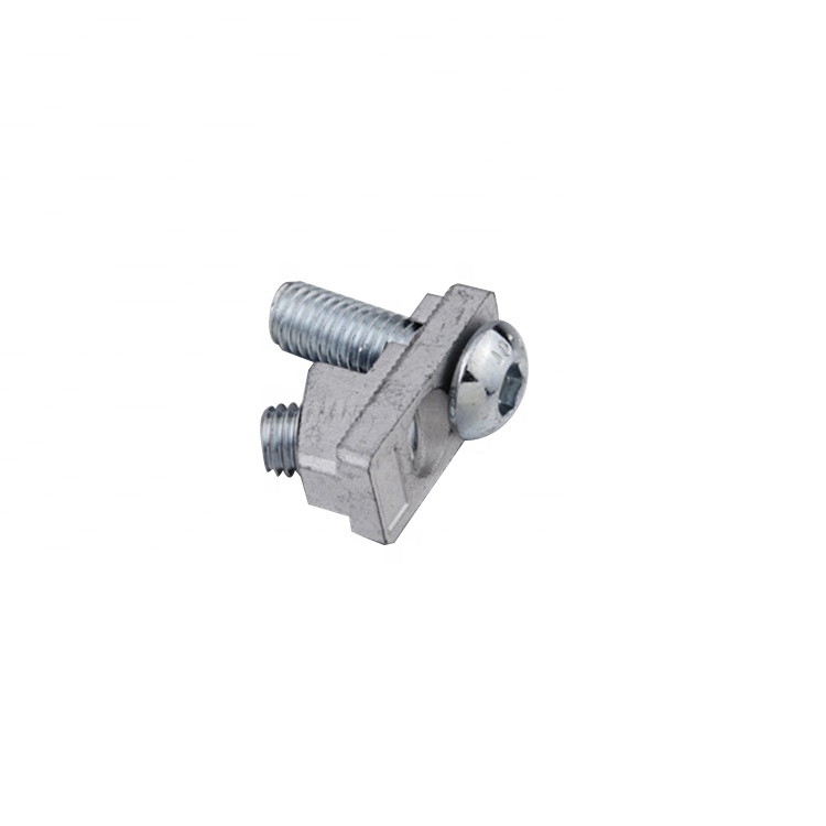
Installing Inner Connectors correctly is essential for building reliable modular assembly systems that perform reliably under load. Proper installation ensures structural integrity, prevents misalignment, and extends the lifespan of your profile joint systems. Whether you are assembling aluminum profiles, steel frames, or other structural components, understanding the correct installation technique will save time, reduce waste, and improve overall system performance.
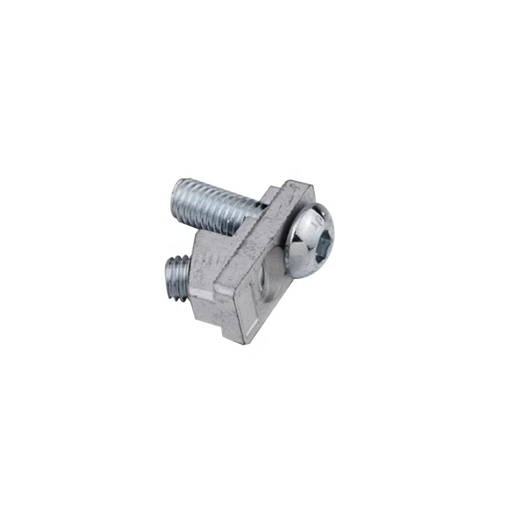
The process of installing internal connection hardware involves more than simply pushing components together. Proper alignment, appropriate force application, and correct sequencing all play critical roles in achieving a secure fit that maintains dimensional accuracy. This guide walks you through the essential steps for installing modular assembly components successfully, covering preparation, installation technique, verification, and troubleshooting common issues that may arise during the process.
Before beginning any installation work, assemble all necessary tools and materials required for the job. You will need a rubber mallet or soft-faced hammer, an assembly press or manual tool for controlled pressure application, measuring instruments such as calipers or rulers, and cleaning materials including soft brushes and lint-free cloths. Having the correct internal connection hardware on hand, along with profile joint systems components and any fasteners specified in your design documentation, ensures you can complete the installation without interruption.
Inspect all inner connectors for damage, surface defects, or contamination before use. Clean the connector surfaces, mating profile surfaces, and assembly components with a soft brush and lint-free cloth to remove dust, debris, or protective coatings. This preparation step prevents binding, misalignment, or jamming during installation and helps achieve consistent results across multiple modular assembly components.
Confirm that your inner connectors match the profile specifications for your project. Check the connector size, material type, and any surface finish requirements against your design drawings. Verify that internal connection hardware dimensions align with the profile channels or cavities where they will be installed, and ensure all modular assembly components are from the same manufacturing batch or specification set to maintain consistency.
Review the installation sequence outlined in your assembly documentation. Profile joint systems often require installation in a specific order to prevent binding or misalignment. Understanding this sequence before you begin prevents installation errors and ensures optimal component fit throughout the assembly process.
Position the profile or assembly frame on a stable, flat work surface aligned with your working height. Insert the inner connector into the profile channel or cavity at a slight angle when necessary, guiding it into position with steady, controlled movements. For modular assembly components, ensure the connector enters the profile square and straight to prevent jamming or edge contact that could cause surface damage.
Apply light pressure to guide the inner connector into its seating position. If resistance is encountered, check for debris, misalignment, or obstruction before continuing. Do not force the connector during insertion, as excessive pressure at this stage may bend, deform, or crack the component. Gentle, deliberate positioning prevents damage and ensures proper seating of internal connection hardware.
Once the inner connector reaches its seating position, apply firm, even pressure using a rubber mallet or soft-faced hammer to fully seat the component. Strike the connector squarely at its center or designated striking surface to distribute force evenly and prevent tilting or binding. For profile joint systems that require precise depth or full engagement, an assembly press provides superior control and ensures consistent results.
Apply pressure gradually while monitoring alignment and fit. The connector should slide smoothly into position without binding or resistance during the final seating stage. If the modular assembly component becomes difficult to seat or stalls, stop immediately and investigate the cause before proceeding. Continuing to force a connector that is not seating properly may result in permanent damage to the connector or the profile.
After seating each inner connector, verify its final position using measuring instruments appropriate for your assembly tolerance requirements. Check that the connector sits flush with the profile surface or at the depth specified in your design documentation. For internal connection hardware in critical load-bearing applications, confirm that the connector is fully engaged and cannot be withdrawn by hand.
Inspect the installed modular assembly component from multiple angles to ensure alignment with adjacent components. Verify that the connector does not protrude or create obstruction for subsequent assembly steps. Document the installation condition and measurement results in your assembly record, particularly for high-reliability or custom applications requiring traceability.
If an inner connector binds or jams during insertion, remove it immediately and inspect both the connector and the profile cavity for debris, burrs, or surface damage. Clean the mating surfaces thoroughly with a soft brush and lint-free cloth. Profile joint systems may occasionally require preliminary cleaning of the profile cavity before component installation. Reposition the inner connector at a slight angle and attempt insertion again with controlled, gentle pressure.
Binding often indicates undersized cavities, dimensional mismatch, or profile surface contamination. Verify the specifications of your internal connection hardware against the profile dimensions listed in the design documentation. If binding persists despite cleaning and repositioning, the connector or profile may be damaged and require replacement. Forcing a binding connector will damage both components and compromise the assembly integrity.
Misaligned inner connectors may fail to seat completely or may sit at an angle within the profile cavity. Remove the connector and examine the profile channel for deformation, damage, or geometric inconsistency. Check that your modular assembly components are oriented correctly according to the assembly documentation. Verify that the profile lies flat on your work surface and is not warped or twisted.
Reinsert the inner connector using careful positioning and visual confirmation of alignment before applying seating force. If repeated attempts to seat the connector fail, the profile cavity may be damaged. In such cases, replace the affected profile section rather than attempting to force the internal connection hardware into an incompatible cavity. Proper seating ensures reliable load transfer and prevents assembly failure during service.
Install inner connectors in the sequence specified in your design documentation or assembly guide, typically beginning at one end of the profile and progressing toward the opposite end. This order prevents connector interference and allows modular assembly components to seat without obstruction. For complex profile joint systems with multiple connectors, grouping installation by profile section or functional module can improve workflow and reduce the risk of misalignment. Always confirm the recommended sequence with your design or technical documentation before beginning work.
Use firm, controlled pressure sufficient to fully engage the inner connector without forcing or over-tightening. A rubber mallet strike or moderate pressure from an assembly press typically seats the connector completely. The specific force requirement varies based on connector size, material, and profile cavity design. If you are uncertain about appropriate force levels for your modular assembly components, consult the manufacturer's technical specifications or conduct a test installation on a non-critical sample. Excessive force may deform or crack the connector, while insufficient force will leave the connector partially seated and prone to loosening.
Yes, inner connectors can typically be removed and reinstalled if necessary. Remove the connector using firm, steady pressure applied in the opposite direction of installation. Clean the connector and profile surfaces thoroughly before reinstalling using the standard installation procedure. However, repeated removal and reinstallation may cause wear or deformation, especially in soft materials or internal connection hardware with tight dimensional tolerances. For critical applications, consider replacing frequently repositioned connectors with new ones to maintain assembly reliability and ensure profile joint systems perform consistently throughout their service life.
2026/09/30
Source aluminum profiles for versatile modular framing. Learn extrusion mechanics, strength benefits & corrosion resistance. Request details.
2026/09/30
Source aluminum profiles for construction projects. Learn structural framing, cladding & window benefits for maximum ROI. Download guide.
2026/09/30
Source optimal aluminum profile sizing techniques. Evaluate load, space, alloy, environment & cost factors to prevent deflection. Download guide.
2026/09/30
Struggling with fastener failures or rework? Master screw sizing by diameter, pitch, material, and load—plus industry-specific standards. Optimize reliability & compliance now.
2026/09/30
Source aluminum profiles for industrial engineering. Discover strength-to-weight ratios, corrosion resistance & 30% cost savings. Download guide.
2026/09/30
Source heat-resistant aluminum profile systems. Master thermal expansion science & stress management strategies for industrial builds. Download guide.